- Why would you do that?
- Designing the gimbal
- Carving the handle
- Wiring the electronic
- Programming the controller
- Next steps
Why would you do that?
After playing Star Citizen for more than
a year, it became evident that I needed to fly with something more immersing
than a mouse and a keyboard.
I made some research and quickly discovered that there are basically two kind of
sensors for the gimbal axis:
potentiometers and Hall-effect
sensors. The first ones are
cheap and easy to employ, but less precise than the second ones, that leverage
magnetic field, and may be trickier to use. As you would expect, cheap joysticks
on the market usually use potentiometers, while expansive ones use Hall-effect
sensors.
The second reason is that it looked like a very fine project to combine multiple
skills: mechanical engineering to build the gimbal, and the whole hardware
thing, electronic for the circuitry, and programming for the firmware. As a
computer science engineer, I knew almost nothing on the two first skills and I
would have to learn a lot.
I must precise that 3D printing was not really an option to me, because I have
no 3D printer, and no easy access to one. Moreover, it was a lot more fun to do
everything on my own, using more traditional techniques.
Designing the gimbal
The most difficult part from a mechanical point of view was of course the gimbal, which in this application is more a universal joint than a true gimbal.
The design is pretty simple, and I did not invent anything here, but I thought it would be fun to cast Zamak for making the pieces, as I had some available, and I know it is pretty easy to meld and cast. For reference, it melds at about 380°C, which is easily reached in a pot on a standard electric hotplate.
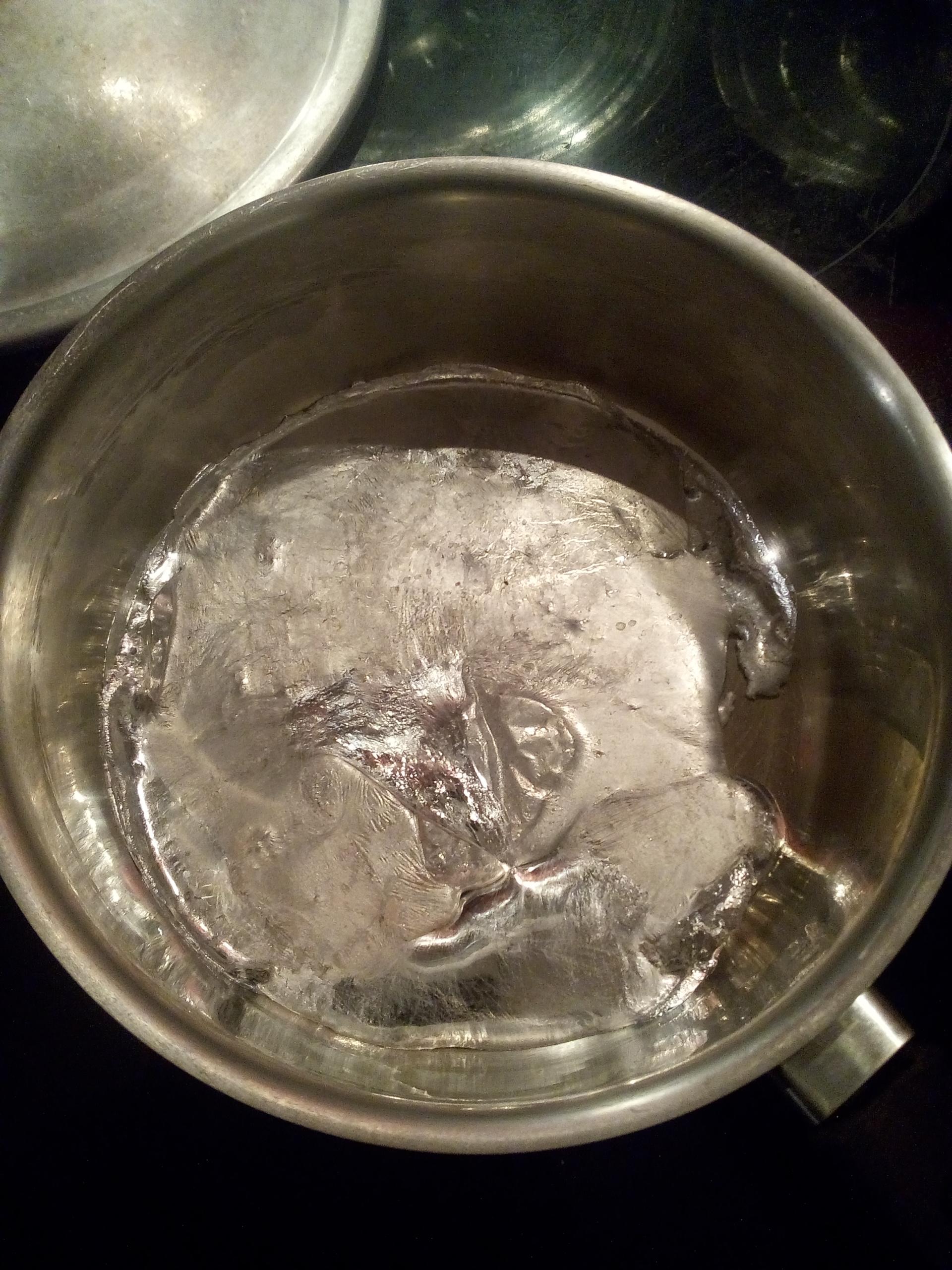
Molten Zamak in a pot
Machining was quickly considered, but it requires more industrial tools to be able to produce multiple identical pieces. It would produce a lot of chip, which is not good for keeping the flat clean, and also has the caveat of generating losses.
Sculpting the pattern
Building the pattern was a very straightforward step. Just melting some candle
paraffin wax, sculpting it with a knife, and I was done.
Sculpting the paraffin wax block
The pattern is ready
Making a re-usable mold, and casting multiple identical pieces
I had already cast some piece in Zamak, but always unique ones, with the mold
being destroyed in the process. Now, I had to make a mold that would be able to
make at least 4 times the same piece. As the draft angle
was not really a functional constraint, and I would have the possibility to
machine it afterwards, I started with
plaster, hoping that it would be easy
to remove the piece from the top.
Plaster drying with the pattern
Indeed, it was easy to remove the piece. Sadly, during the multiple tries, the
mold always ended-up being fractured by the hot temperature of the metal. It was
time to try something else.
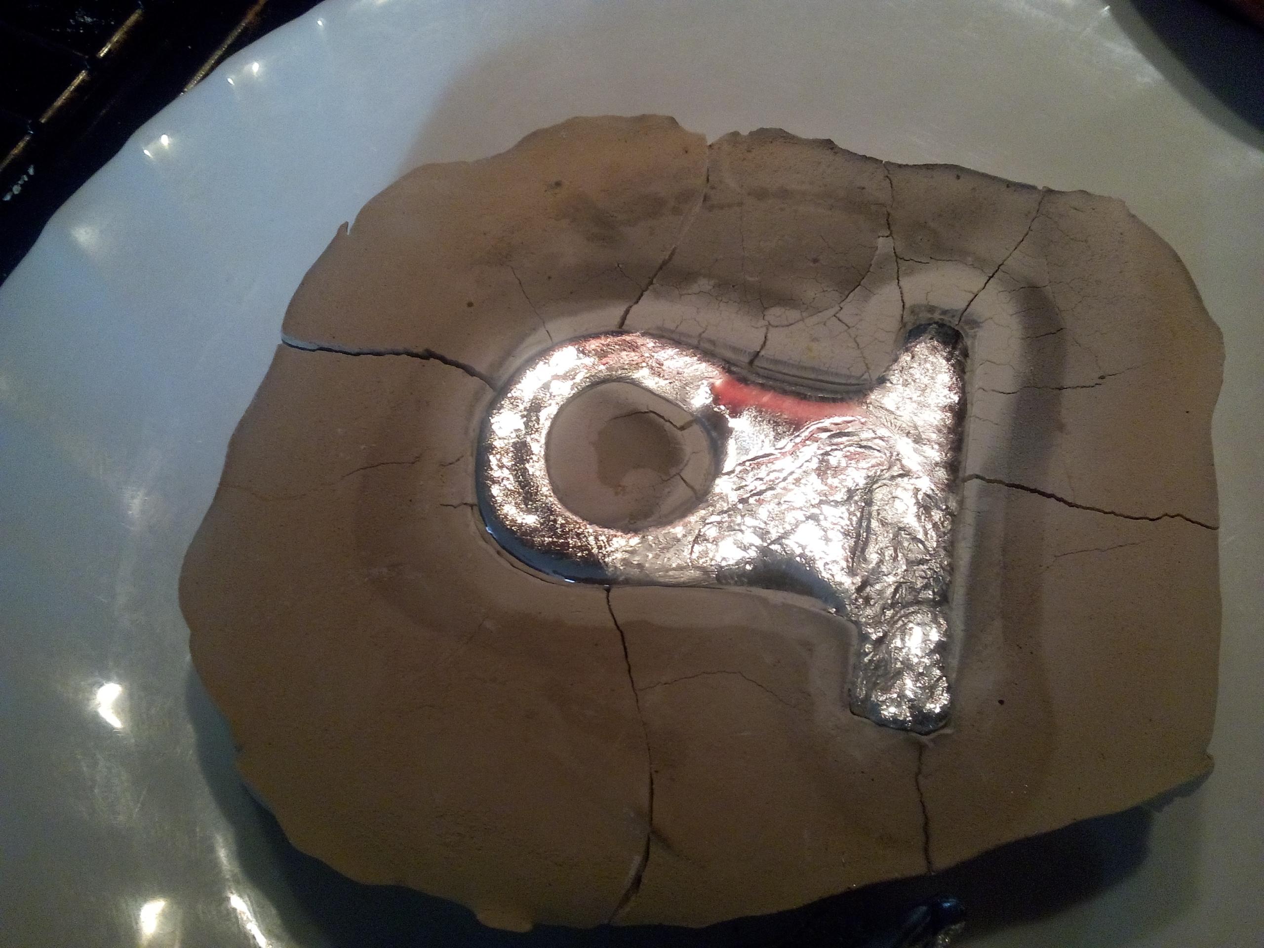
A first broken mold
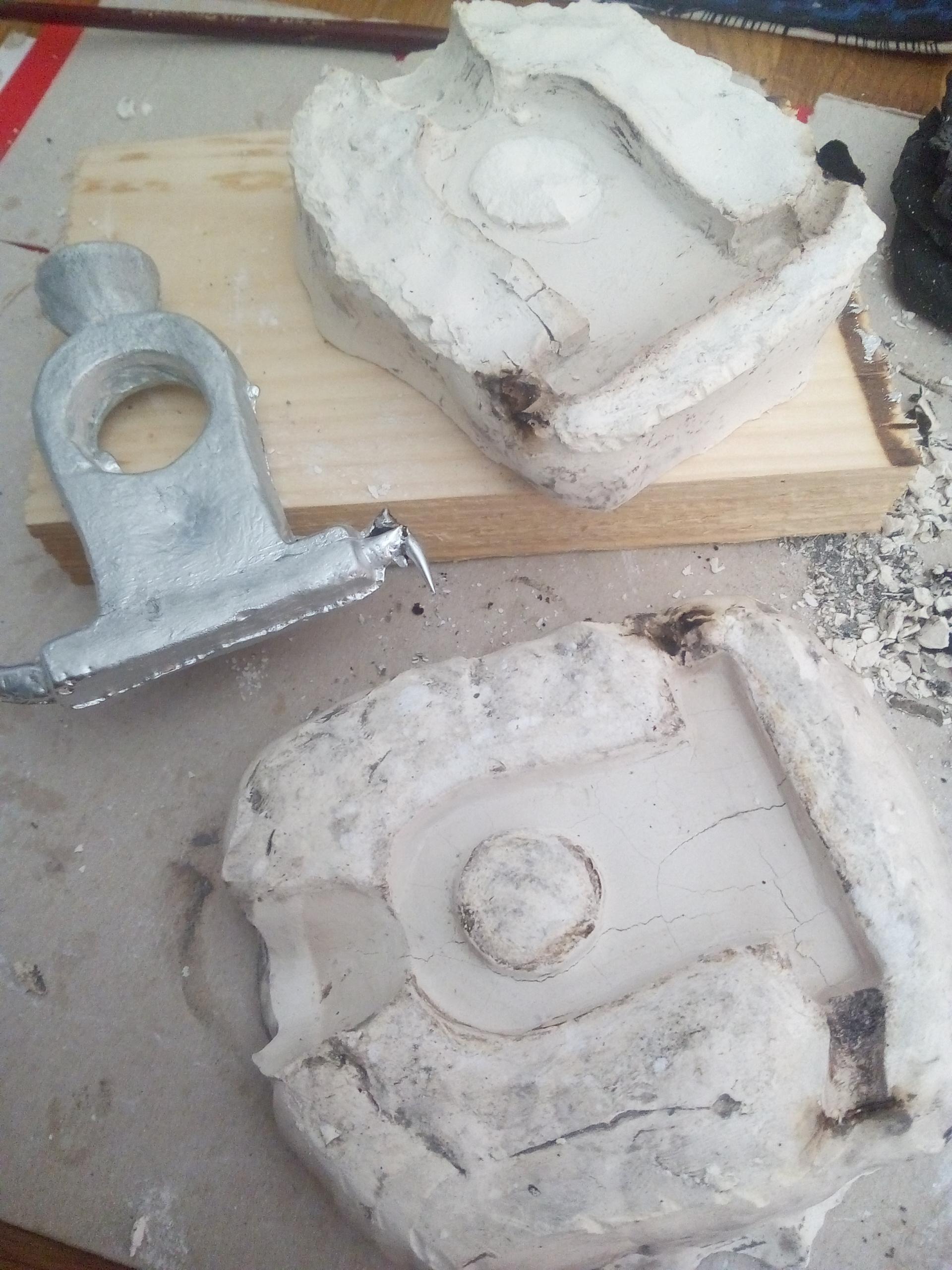
A second mold that did not make it
Looking for solutions on the Internet, I stumbled upon this
video made by a fisherman, that
shows how to make a mold to cast lead using RTV
silicon. Thankfully, lead and zamak
have similar melting points, usually around 350°C and 400°C, depending on the
alloys, meaning I should be able to use the same technique. RTV Silicone is not
that hard to find, and this one
worked pretty well!
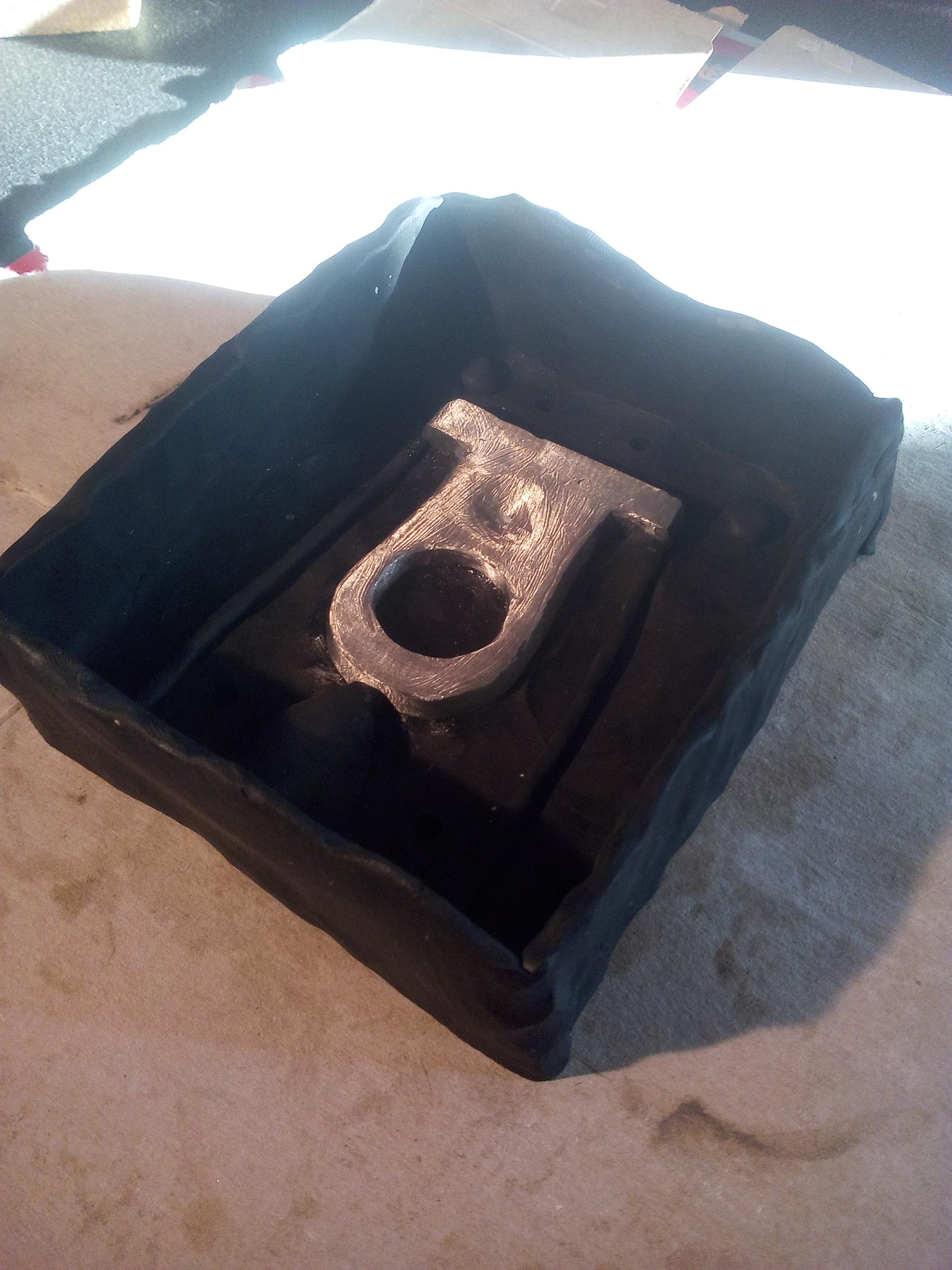
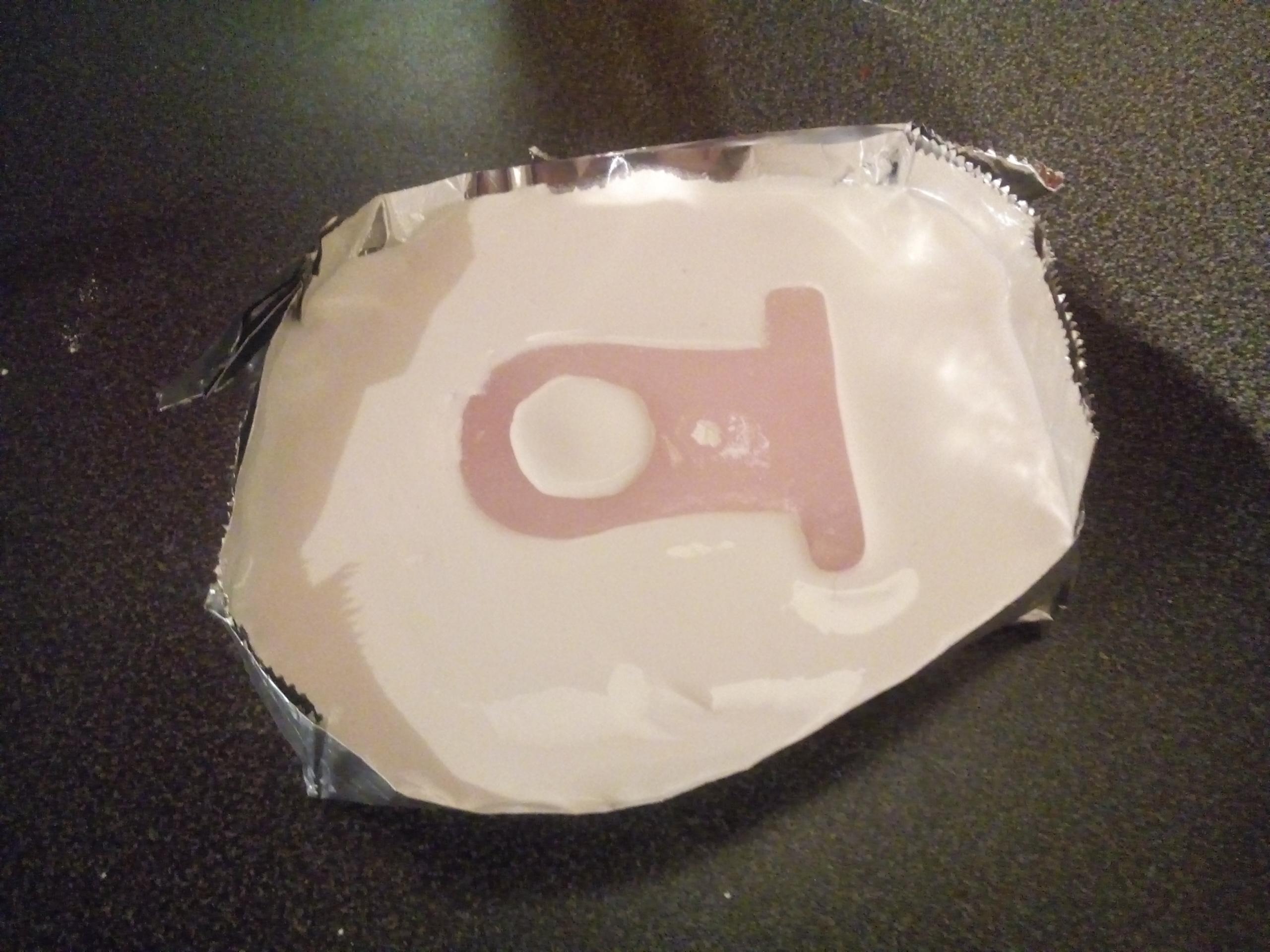
A Zamak pattern made from the previous steps, ready to get the silicon for a new mold.
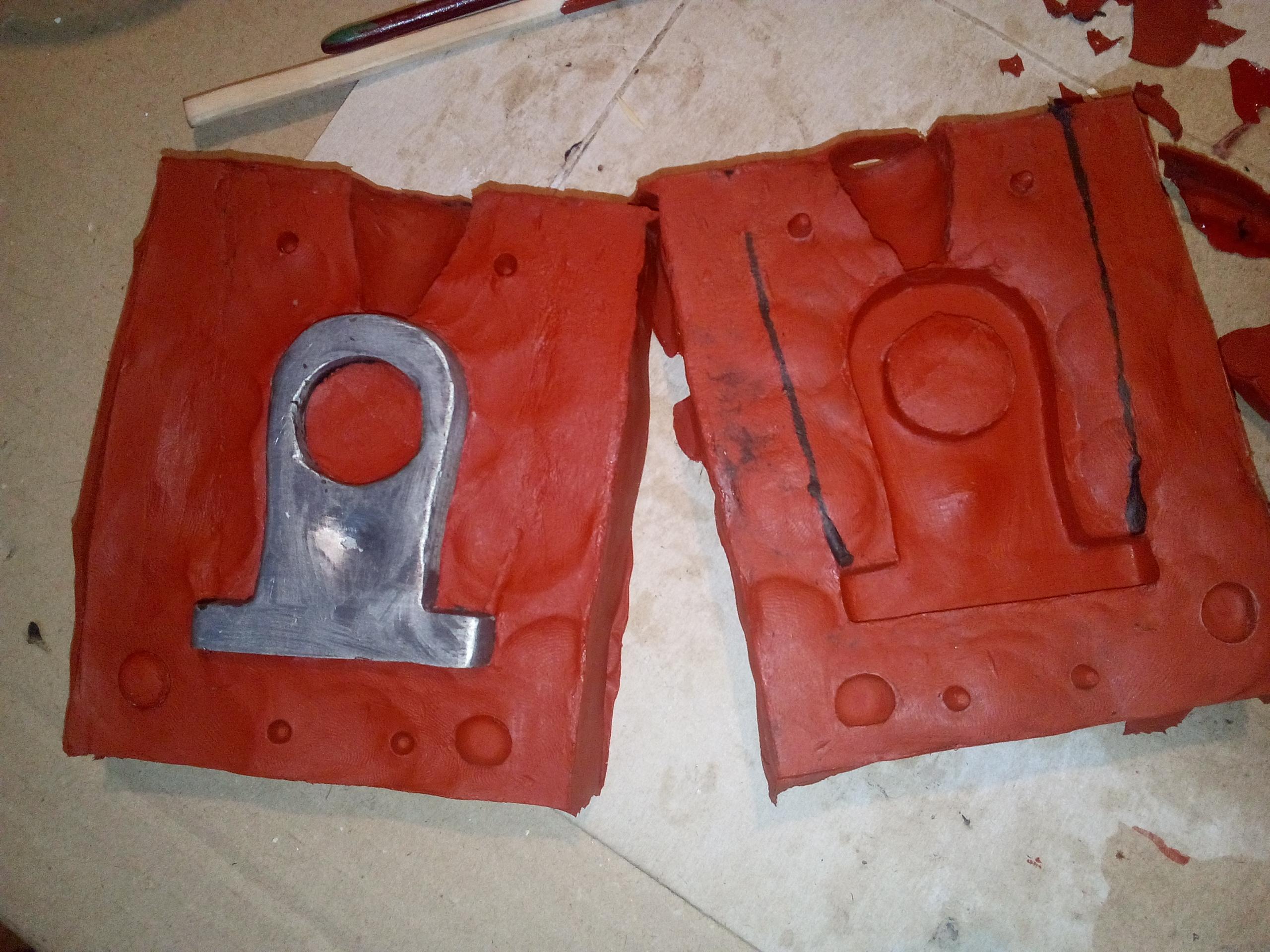
The second part of the silicon mold is almost ready.
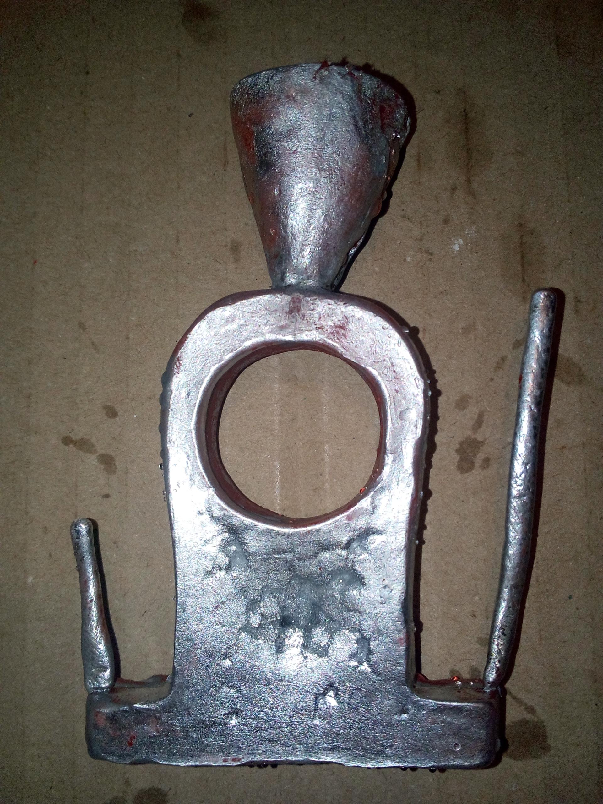
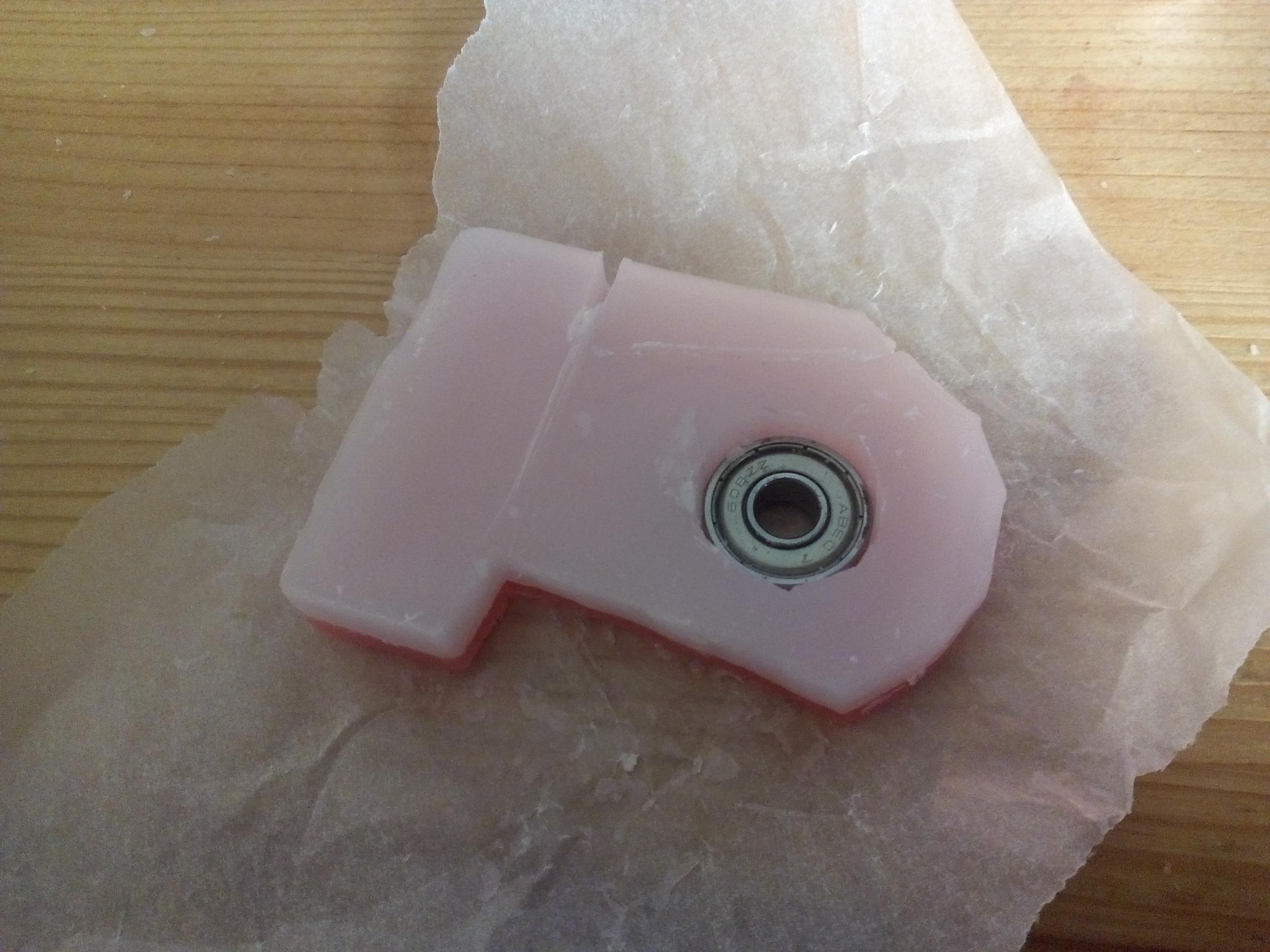
One piece of the gimbal, freshly cast.
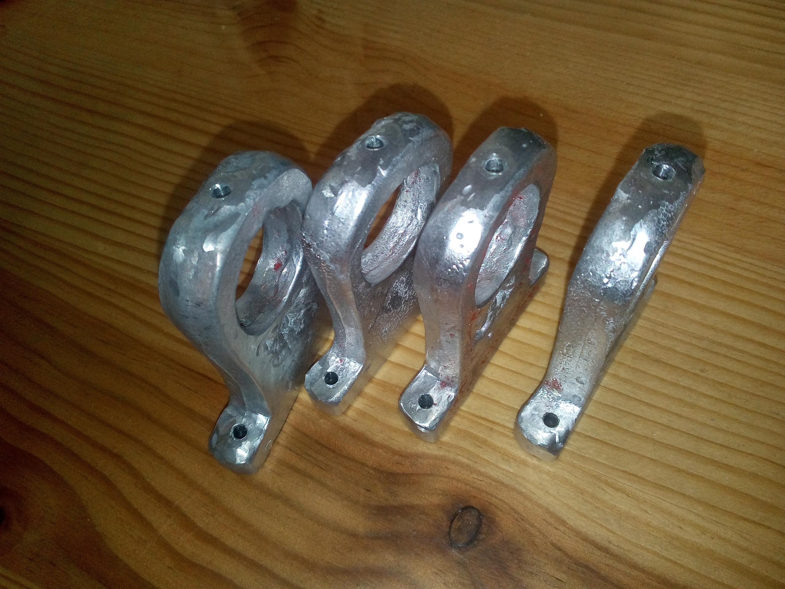
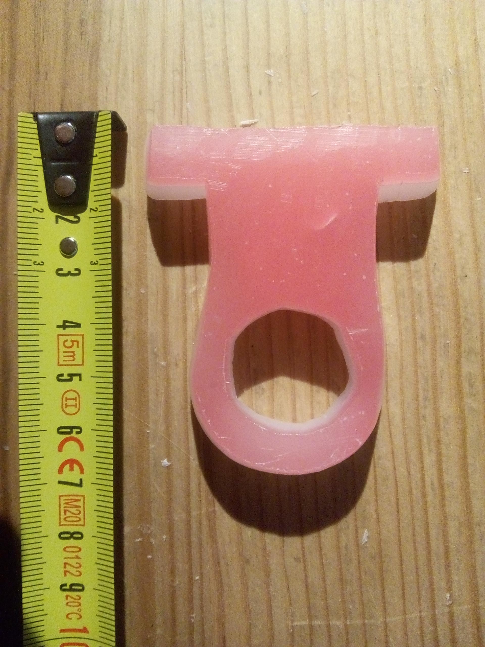
The four gimbal pieces, once polished and drilled.
Assembling the gimbal and testing the sensors
Now that I had most of the pieces for the gimbal, I tried to assemble it a first time to test the sensors and make a first proof-of-concept.
The assembly was pretty simple, with the X and Y axis being hold on some old inline-skates bearing that I salvaged. The axis themselves are made with two bits of 8mm threaded rod tied together with iron wire.
For the test, I just flashed a simple program that
just printed the analog values to the serial output.
Those values are physically an electric tension, varying between 0V and 5V
(theoretically). Once read by the analog input pin of the Arduino, they are
represented by a positive integer varying between 0 and 1023.
On the measurements I've made with the test program, I've managed to get the
following values, which are, in my opinion, completely satisfying in terms of
accuracy and range:
| X | Y | Z | |
|---|---|---|---|
| Min | 130 | 155 | 330 |
| Max | 835 | 950 | 730 |
| Range (Max-Min) | 705 | 795 | 400 |
X and Y have very decent ranges, which is super great, but in any case, the sensors are so precise, that the step between two values is only one, if I move the stick gently enough. Clearly, at last 400 different values, and up to 795, are more than enough for me to fly anything in any game! I'm also not sure about what level of flying would require more precision.
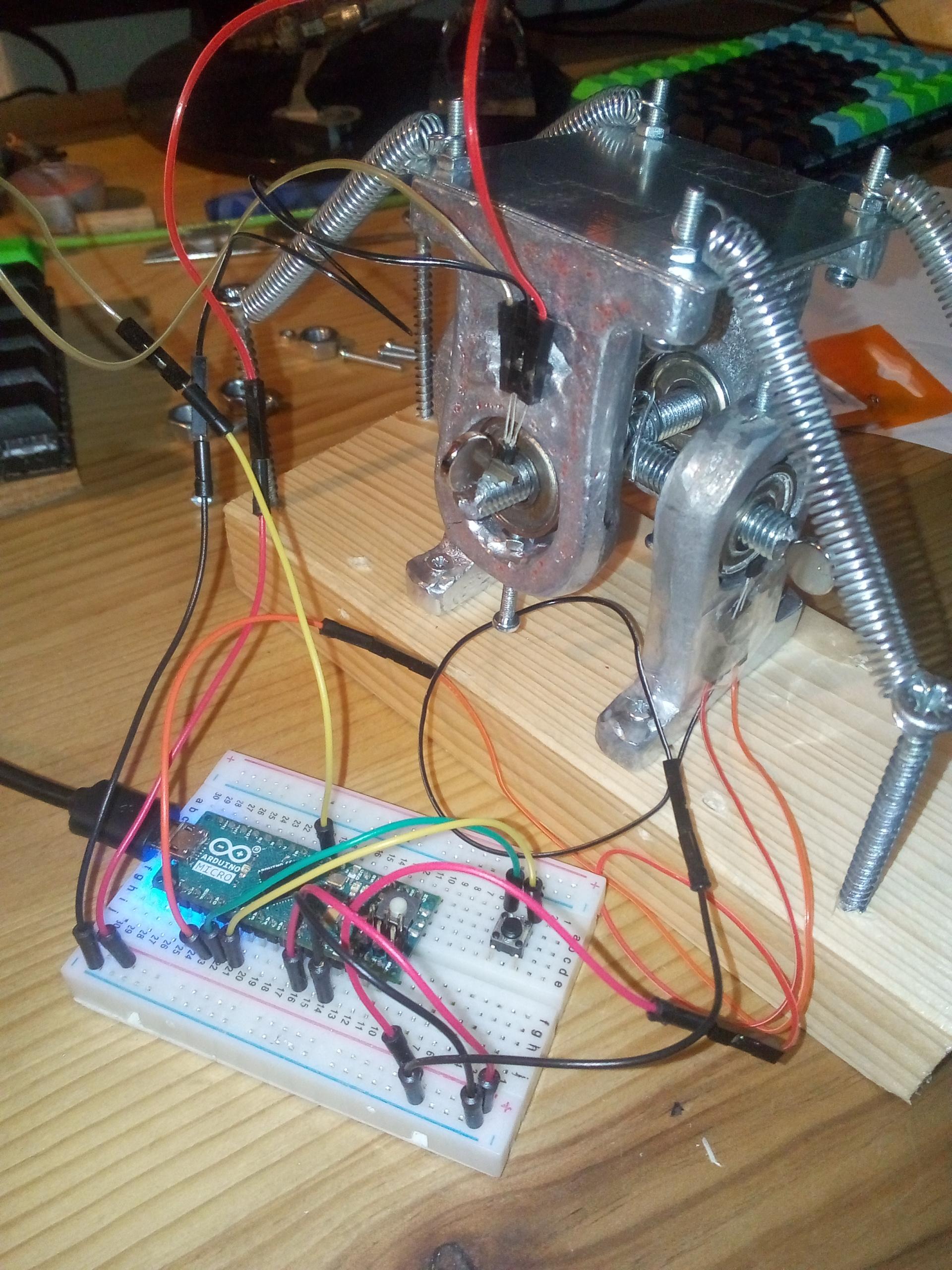
Gimbal is first assembled.
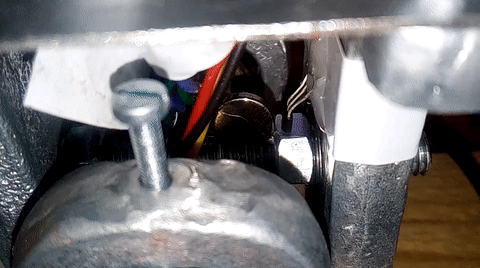
A sensor and its magnet in the final state after the adjusments.
Carving the handle
It happened that I had a boxtree branch
available. Boxwood is a very fine wood to carve, and the diameter of the branch
was perfect for sculpting a handle, while passing some wires inside it for the
buttons. I am quite happy with the result of the handle itself, but the
revolute-joint that binds it to the gimbal is currently not at its best.
Reworking that part is already planned.
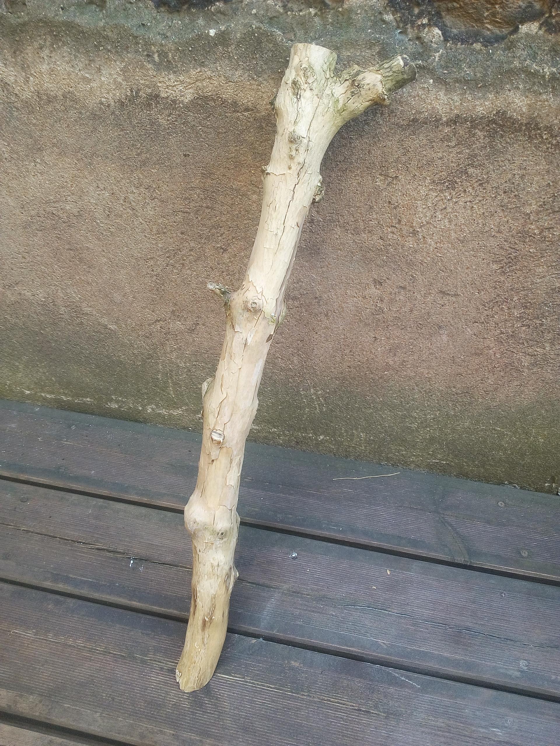
The piece of boxwood before anything happened.
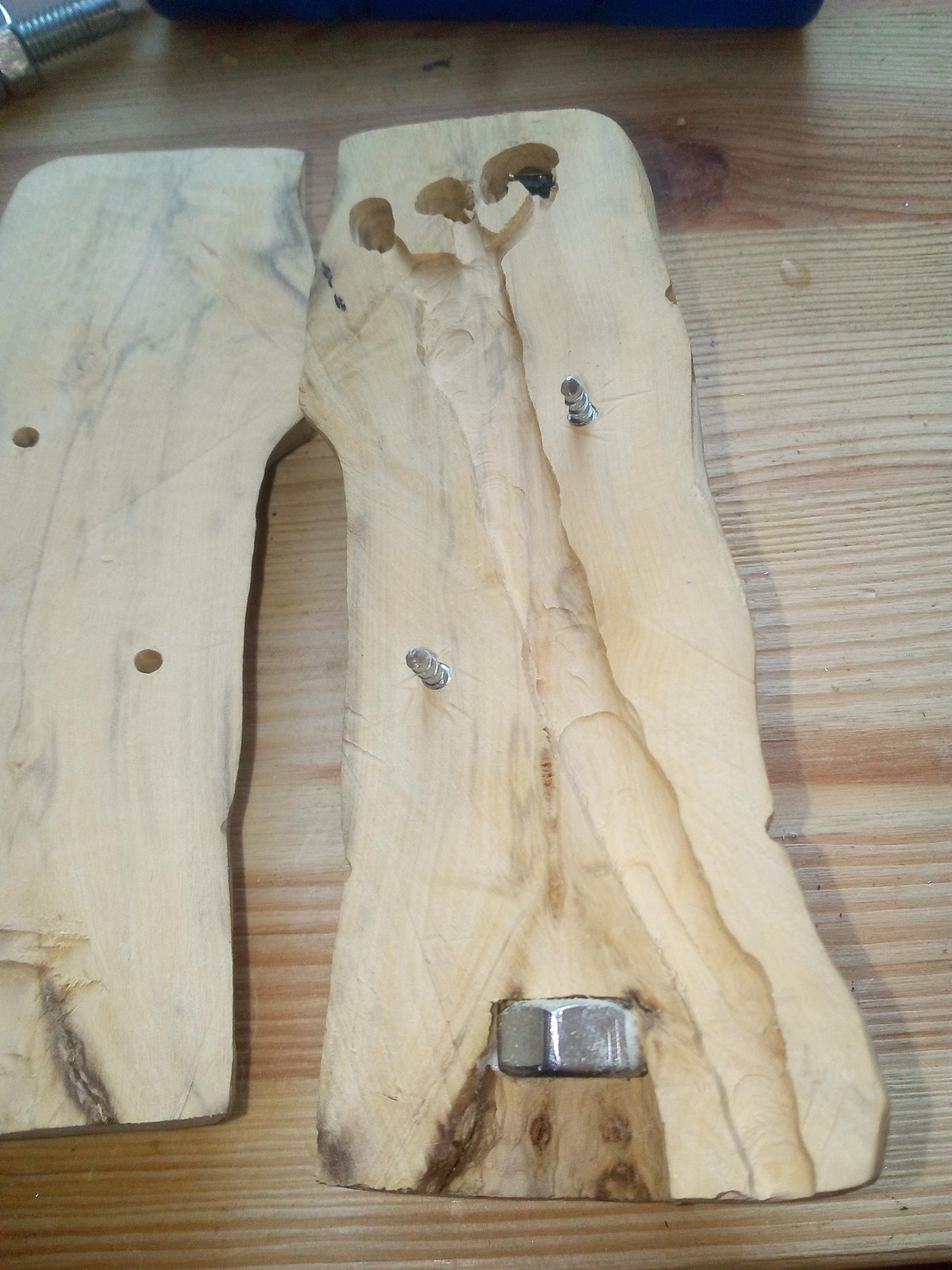
Carving the inside of the handle, to make place for the wires.
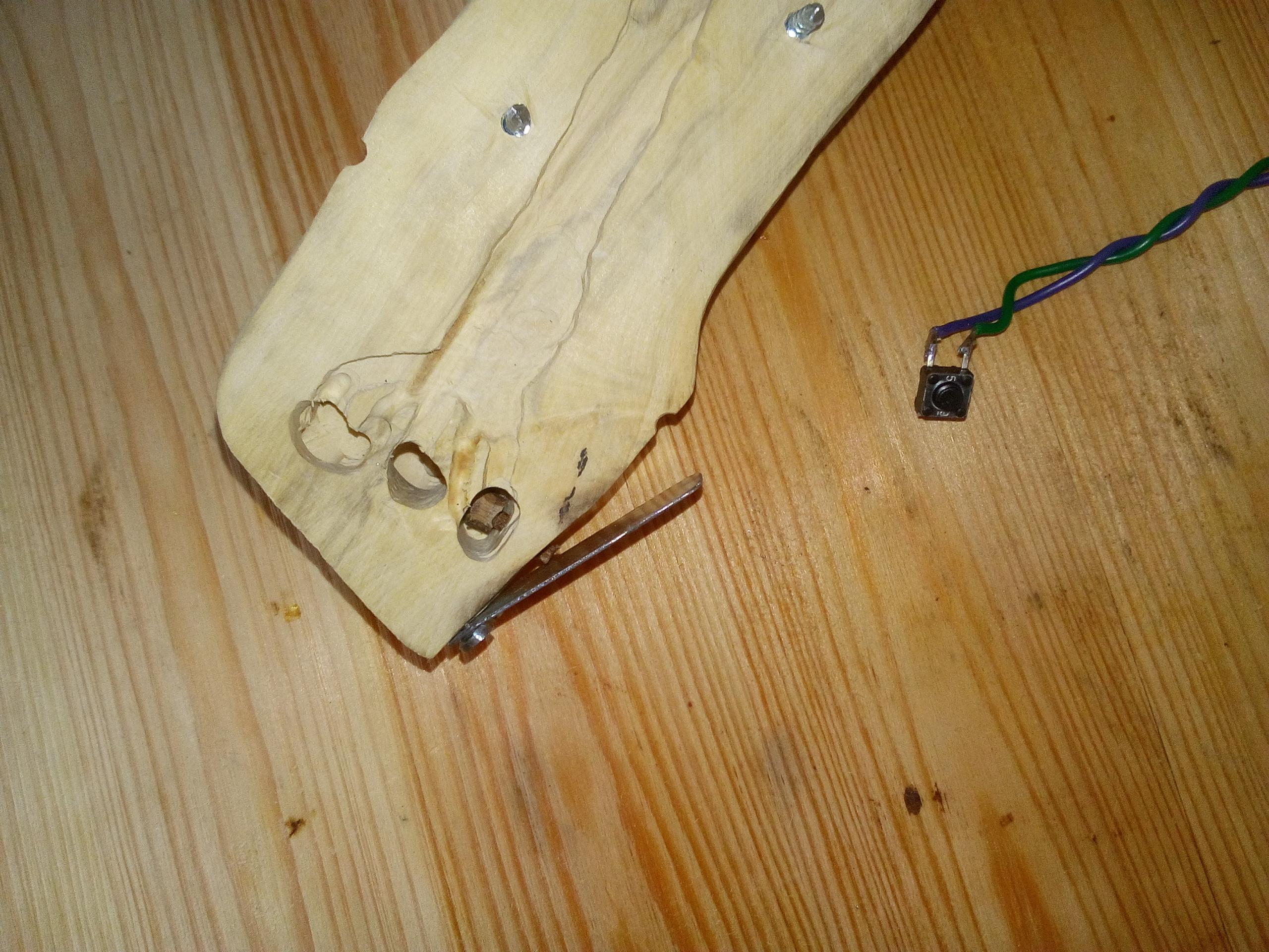
A button, ready to be put in place behind the trigger.
Wiring the electronic
Nothing really fancy here, the electronic is really simple.
Hall-effect sensors are wired the same way potentiometers are. That means a pin to the ground, a pin to the +5V, and the third pin will be the output tension, that must be connected to an analog input of the Arduino micro.
For the buttons, using the QMK firmware makes wiring a diode matrix possible.
This allows a great number of switches on a very small number of inputs on the
controller.

Schematics
Download schematics
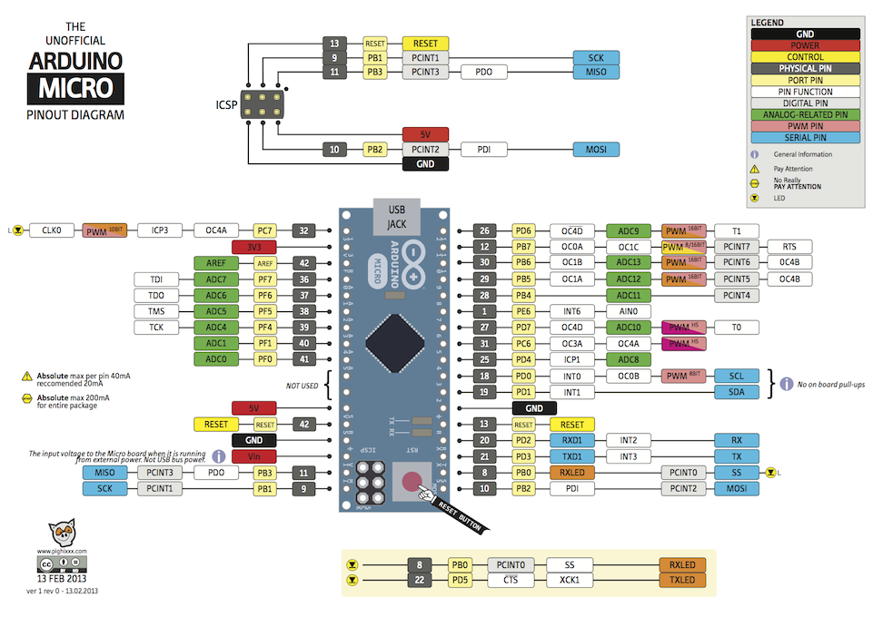
Arduino micro pinout diagram
Programming the controller
At the very beginning of this project, I had already found this pull-request
in the QMK firmware project, which I had tested on my
BFO-9000,
leveraging the virtual axis feature to fly ships using a keyboard recognized as
a joystick by Star Citizen (most games would work too).
While this worked pretty bad for flying (spoiler alert: discrete, all or none
axis are not that great!), this gave me confidence that the real analog axis
would work fine too from the game's point of view.
By the time I had the joystick assembled for the first time, the PR had even been merged, and was fully functional! Here is my firmware code at the time of writing.
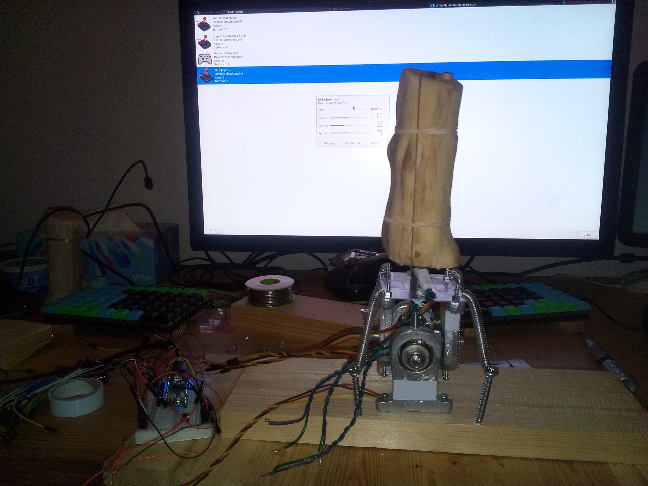
Calibrating the joystick using jstest-gtk
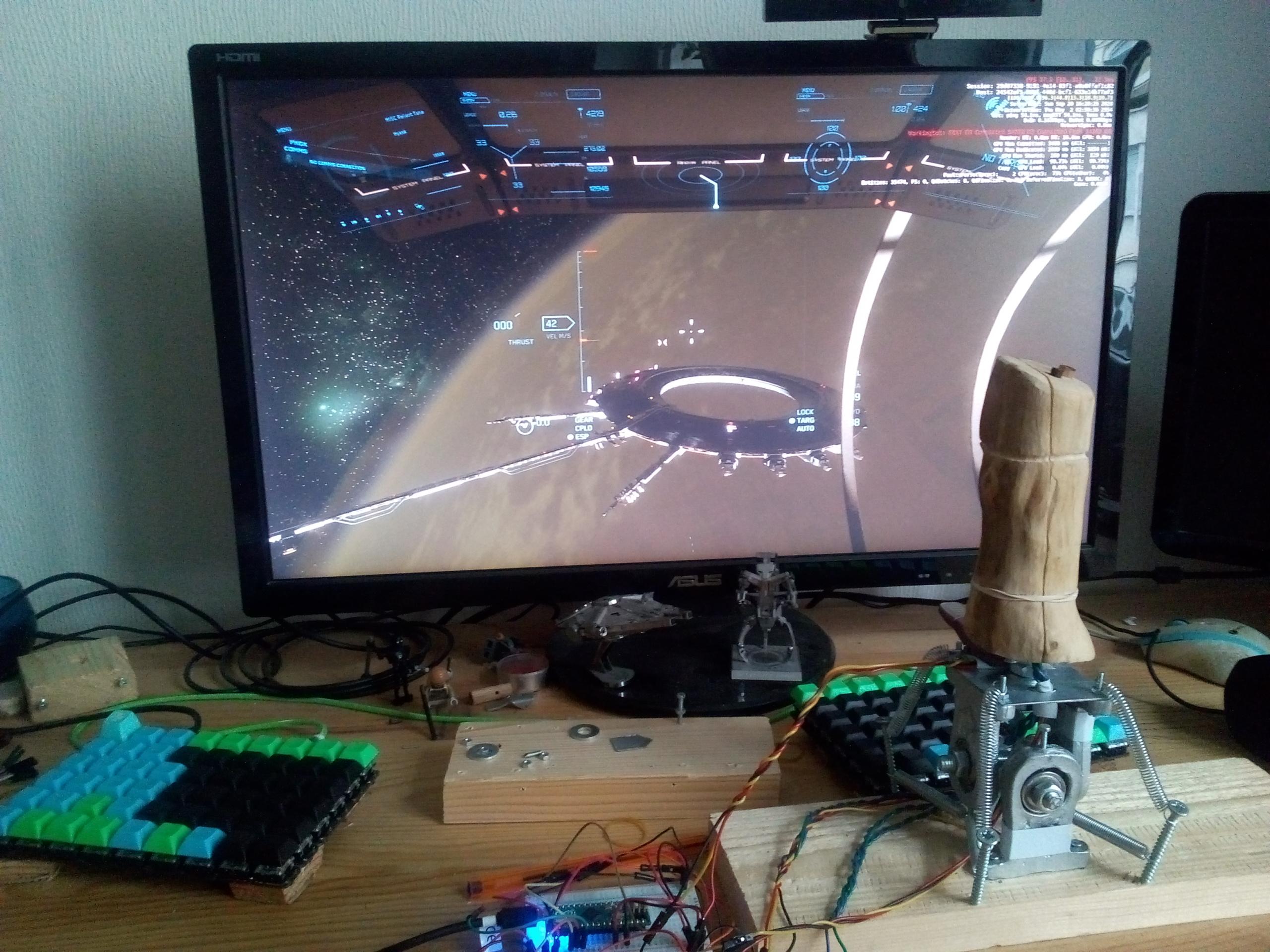
Finally testing the joystick in game!
For those who want to see more pictures, here is a gallery with photos of all the building steps.
Next steps
Even if the joystick is currently working, it's still a very early prototype that needs improvements. Here are some of them that I already thought of:
- Mount the stick on a proper bearing for less play and smoother feeling.
- Make an adjustable spring system, for fine tuning the rest position.
- Make a case around the gimbal to protect the wiring, and host more buttons.
- Mount everything on a decent metal plate instead of a thin wooden plank.
- Build a second joystick to handle 3 more axis!